Every standard USB cable contains four inner wires that carry power and data between your devices. If you're splicing a broken cord, building a custom charging rig, or troubleshooting a data transfer issue, knowing how these internal lines connect is essential. USB architecture relies on a standardized color code and pinout configuration that remains consistent across classic USB 2.0 specifications.
Understanding this layout prevents reversed polarity, which can fry sensitive microcontrollers or phone ports. This guide breaks down the exact pin configurations, standard wire color codes, safety precautions, and step-by-step splicing instructions so you can wire USB connections accurately.
USB 2.0 Pinout and Standard Color Codes
Classic USB 2.0 cables use a four-wire system. Inside the outer braided shielding and foil wrap, you will find four distinct wire colors. Each color corresponds to a specific pin inside the standard Type-A or Type-B connector.
- Red (VBUS): Carries positive 5 volts of DC power to power connected peripherals.
- White (D-): Data negative line used for differential data signaling.
- Green (D+): Data positive line paired with the white wire for bidirectional communication.
- Black (GND): Ground wire completing the electrical circuit.
In addition to these four wires, many cables include a bare copper wire called the drain wire. This wire connects directly to the metal outer shell of the USB plug to ground EMI shielding and reduce electromagnetic interference.
Connector Pinout Reference
Looking at the front of a standard USB Type-A male plug with the plastic tongue facing downward, the pin numbers run from right to left:
- Pin 1 (Right): VBUS (Red, +5V)
- Pin 2: D- (White, Data Minus)
- Pin 3: D+ (Green, Data Plus)
- Pin 4 (Left): GND (Black, Ground)
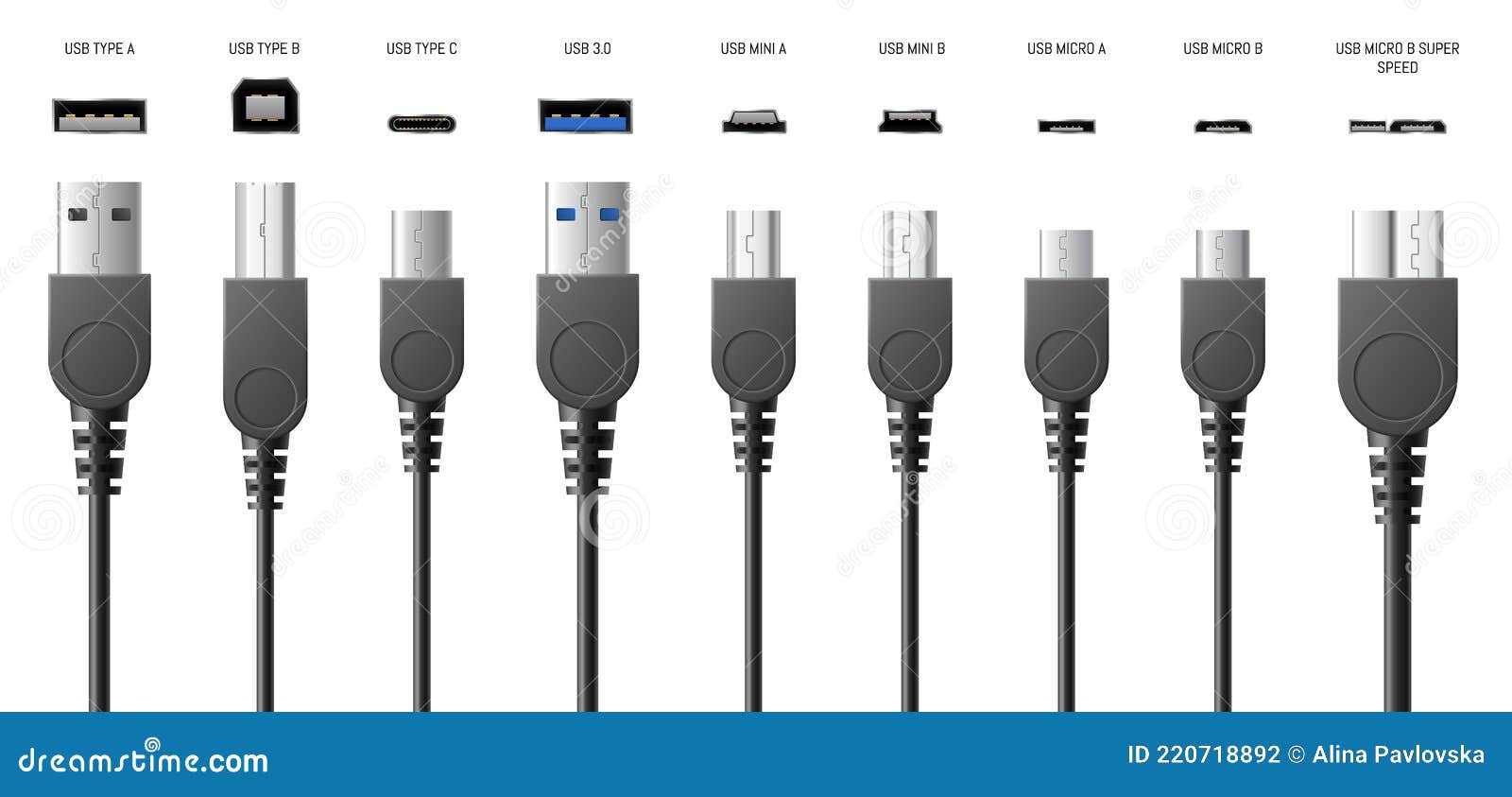
If you are working with older mini-USB or micro-USB connectors, the pinout expands to five pins to accommodate an ID pin for On-The-Go (OTG) host detection, but the core four power and data wires retain the same color codes. For deeper technical specifications on serial bus standards, you can review documentation provided by the USB Implementers Forum.
Tools and Materials for Splicing USB Cables
Working with USB wiring requires precision because the internal conductors are fragile, often made of fine stranded copper wire equivalent to 28 AWG or thinner. Gathering the right tools before you start ensures a durable, functioning connection.
- Wire strippers: Precision strippers rated for 28 to 30 AWG wire.
- Soldering iron and rosin core solder: For permanent, low-resistance electrical joints.
- Heat shrink tubing: Various diameters to insulate individual wires and the outer bundle.
- Multimeter: Essential for continuity testing and verifying voltage before plugging equipment in.
- Utility knife or razor blade: For carefully slicing away the outer PVC jacket and foil shielding.
Preparing the Cable
Start by sliding a 2-inch piece of large-diameter heat shrink tubing over one end of the cable. You must do this before soldering the internal wires, otherwise you won't be able to slide it into place afterward.
Strip back about one inch of the outer PVC jacket using your utility knife. Take care not to nick the inner insulation of the red, white, green, and black wires. Unravel the braided shielding and fold back the aluminum foil shield. If your cable includes a drain wire, twist it together with the bare shielding strands.
Strip about one-quarter inch of insulation from the ends of the four inner wires. Twist the exposed fine strands tightly between your fingers to prevent stray strands from causing short circuits.
Step-by-Step Guide to Splicing a USB Cable
Whether you are repairing a frayed charging cord or creating a custom power adapter, following a structured process guarantees success.
- Slip heat shrink tubing in place: Slide small individual pieces of heat shrink tubing over each of the four separate wire strands. Keep them pushed back away from the bare ends so heat from your soldering iron doesn't shrink them prematurely.
- Tin the wire ends: Apply a small amount of solder to the exposed copper strands of each wire. This process binds the fine strands together, making it much easier to join them to their matching counterparts.
- Match color to color: Align the red wire to red, white to white, green to green, and black to black. Slide the wires together so the tinned ends overlap securely.
- Solder the connections: Touch your soldering iron tip to the twisted joint and feed a small amount of solder into the joint until it flows smoothly around the copper. Remove the iron and let the joint cool without moving it.
- Insulate individual wires: Slide the individual pieces of heat shrink tubing over the freshly soldered joints. Use a heat gun or the side of your soldering iron to shrink them tightly around each wire.
- Shield and reinforce: Wrap the braided shielding and drain wire back over the soldered core. If you have a separate ground connection for the shield, secure it now. Slide your large outer heat shrink tubing over the entire repair area and shrink it down for structural support.
For general electrical safety guidelines when working with low-voltage DC circuits, consult resources from the Occupational Safety and Health Administration.
Common Mistakes and Troubleshooting
Even experienced DIYers run into issues when working with USB wiring due to the tiny scale of the components.
- Reversing polarity: Accidentally swapping the red (5V) and black (GND) wires delivers power backwards to your connected device, which can instantly ruin internal components or trigger motherboard protection circuits. Always double-check with a multimeter before plugging anything into a live USB port.
- Skipping individual wire insulation: If bare soldered joints touch each other inside the cable jacket, you'll create a short circuit. Always insulate every single wire individually before applying the outer sleeve.
- Cold solder joints: A dull, grayish, or ball-shaped joint indicates a cold solder joint that will crack under tension. Reheat the joint until the solder flows bright and smooth.
- Ignoring data line twists: On long custom cables, twisting the white and green data lines around each other is critical. This twisted-pair geometry cancels out electromagnetic noise. Straight, parallel data wires suffer from signal degradation and data packet loss.
Frequently Asked Questions
Can I use a USB cable for power only without data?
Yes. If you want to build a dedicated charging cable, you only need to connect the red (VBUS) and black (GND) wires. Leave the white and green data lines cut, stripped, and individually insulated so they don't touch anything.
Why does my spliced cable charge my phone slowly?
Thin wire gauges have high electrical resistance over long distances. If your replacement cable uses extremely thin copper strands, voltage drop occurs along the line, causing the connected device to drop down to a lower charging amperage.
What is the purpose of the bare wire in a USB cable?
The bare wire is the drain wire. It maintains continuous contact with the outer foil and braided metal shield, channeling static buildup and external electrical interference away from the internal data lines.
Can I splice a USB 2.0 cable into a USB 3.0 cable?
You can splice power and ground wires across different versions because VBUS and GND remain standard. However, USB 3.0 adds five extra wires for SuperSpeed data transmission. You cannot mix USB 2.0 and USB 3.0 data lines to achieve high-speed data transfer rates.