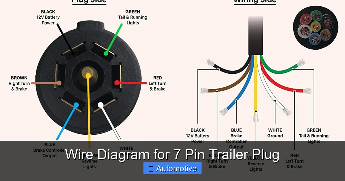
Getting your trailer brakes to engage reliably starts with matching the correct wires from your tow vehicle to the plug on your trailer tongue. If you get the pin configuration wrong, your trailer brakes won't activate when you press the pedal, or worse, your running lights and turn signals will short out.
A trailer brake wiring diagram maps out how electrical current flows from your vehicle battery, through the brake controller, out the trailer plug, and into the electromagnetic drums on your trailer axle. Whether you're working with a standard 4-way flat plug or a heavy-duty 7-way blade connector, understanding pin functions, wire gauge sizes, and grounding prevents roadside failures.
Decoding Trailer Plug Pinouts
Standard vehicle-to-trailer connectors use specific color-coded wires and pin locations. Knowing what each pin does is the first step in diagnosing an electrical fault or installing a new socket from scratch.
- 7-Way Round Blade Connector: This is the standard for larger trailers equipped with electric brakes. It handles 12V power, electric brakes, running lights, left turn/stop, right turn/stop, backup lights, and a heavy-duty ground wire.
- 4-Way Flat Connector: Common on smaller utility trailers without brakes. It only carries running lights, left turn/stop, right turn/stop, and ground. It cannot power electric brakes.
- 5-Way Flat Connector: Adds a blue wire for surge brake reverse lockout solenoids to the standard 4-way setup.
When looking at a 7-way blade socket on your vehicle, the center pin typically handles backup lights, while the surrounding blades control braking, lighting, and auxiliary power.
Standard Wire Color Conventions
While aftermarket wiring harnesses can sometimes use non-standard colors, North American manufacturing standards follow a reliable color code. Let's look at what each color represents in a typical 7-way or 4-way setup:
- Black Wire: 12-volt auxiliary power running from the vehicle battery to charge a breakaway battery or power interior trailer accessories.
- Blue Wire: Electric trailer brake feed. This carries modulated voltage from your in-cab brake controller directly to the trailer's magnet assemblies.
- White Wire: Main ground wire. A weak ground is the number one cause of flickering lights and sluggish trailer brakes. It should be bolted directly to bare metal on the vehicle frame and trailer tongue.
- Brown Wire: Tail, marker, and license plate lights.
- Yellow Wire: Left stop and left turn signal.
- Green Wire: Right stop and right turn signal.
If your wires don't match these colors, always test continuity with a digital multimeter rather than guessing based on jacket color alone.
Installing and Connecting a Brake Controller
Electric trailer brakes require an electronic brake controller mounted inside the cab of your tow vehicle. This unit senses deceleration or hydraulic pressure and sends the correct amount of electrical current to the blue brake wire.
First, mount the controller securely under your vehicle's dash within easy reach of the driver. Run a dedicated power wire protected by a circuit breaker (usually 20 to 30 amps) directly from the positive battery terminal to the controller's input. Connect the controller's output wire to the blue wire running to the rear 7-way socket.
Modern vehicles often feature built-in factory brake controllers or a designated plug under the dash that accepts a quick-connect adapter harness, cutting down installation time significantly. For more details on safe towing weights and setups, consult the NHTSA Towing Safety Guidelines.
Common Wiring Mistakes to Avoid
Even experienced DIYers make errors when splicing or routing trailer wiring. Avoiding these pitfalls saves you from blown fuses and failed inspections:
- Using the vehicle frame as the sole ground for high-draw brakes: Electric brake magnets draw significant amperage. Always run a dedicated ground wire back to the battery or ensure the frame-to-chassis bonds are completely free of rust and paint.
- Undersizing wire gauge: Using thin 16-gauge wire for electric brakes causes voltage drop over long trailer tongues, resulting in weak braking performance. Use at least 10-gauge or 12-gauge wire for brake and power feeds.
- Neglecting weatherproof connections: Standard twist-on wire nuts will corrode within weeks underneath a trailer. Use heat-shrink butt connectors, solder, and dielectric grease to seal every joint against moisture and road salt.
Frequently Asked Questions
Can I hook up electric trailer brakes to a 4-way flat plug?
No. A 4-way flat plug only transmits lighting signals and ground. Electric trailer brakes require a dedicated 12V power feed and a brake controller output wire, which necessitates upgrading to a 7-way blade connector.
Why are my trailer brakes humming when I turn the key?
A low humming sound when the key is on and the brake pedal is depressed is normal. It means current is flowing to the electromagnets inside the brake drums. If the hum is extremely loud or smells like burning insulation, check for a short circuit or a stuck brake controller.
How do I test if my trailer brake magnets are working?
Disconnect the trailer plug from the vehicle and use a 12V battery source to apply power directly to the blue brake wire and ground. You should hear a distinct click at each wheel hub, and if you hold a steel screwdriver near the outside of the hub, magnetic pull should hold it in place.
What wire gauge should I use for electric trailer brakes?
For the main brake feed running from the axle junction back to the plug, use 10-gauge or 12-gauge copper wire to minimize electrical resistance and ensure full braking power reaches the magnets.